
A circuit which allows a connected motor to operate in clockwise and anticlockwise directions through alternate input triggers is called a bidirectional controller circuit.
The first design below discusses a Full bridge or H bridge based Bidirectional motor controller circuit using the 4 opamps from the IC LM324. In the second article we learn about a high torque bidirectional motor controller circuit using IC 556
介绍
Generally,mechanical switchesare accustomed to adjust the direction of rotation of a DC motor. Adjusting the polarity of the utilized voltage and the motor rotates the opposite direction!
On one hand this may have the drawback that a DPDT switch requires to be added to alter the polarity of the voltage, but we have deal with only a switch which makes the procedure quite easy.
但是,DPDT可能会有一个严重的问题,不建议您在旋转运动过程中突然将电压扭转。这可能会导致当前的尖峰,这可能会烧掉相关的速度控制器。
Furthermore, any kind of mechanical stress can also bring about similar issues. This circuit beats these complications easily. The direction and speed is manipulated with the help of a solitary potentiometer. Rotating the pot in a specified direction causes the motor to begin rotating.
Switching the pot in the opposite direction enables the motor to rotate in the reverse motion. The middle position on the pot switches OFF the motor, ensuring that the motor slows down first and then stops before an effort is made to change the direction is made .
Technical Specifications
Voltage:The circuit and motor make use of the common power supply. This implies that because the highest working voltage of theLM324is 32VDC this likewise becomes the maximum voltage accessible to operate the motor.
Current:IRFZ44 MOSFET专为49A设计;IRF4905将能够处理74A。然而,从MOSFET引脚到螺丝端子块的PCB轨道只能管理约5A。通过在PCB轨道上焊接铜线件可以改善这一点。
In that case make sure that the MOSFETs do not become too hot - if they do then larger heatsinks will be needed to be mounted on these devices.
LM324 Pinouts

使用LM324对直流电动机的双向控制
Fundamentally, you will find 3 ways toadjust the speed of DC motors:
1.By using mechanized gears to attain the ideal acceleration:This approach is often over and above the convenience of the majority of enthusiast practicing in home workshops.
2.Decreasing the motor voltage through a series resistor.This can be certainly inefficient (power will be dissipated in resistor) and also result in the reduction in torque.
The current consumed by the motor also heightens as the load on the motor increases. Increased current means a more voltage drop over the series resistor and hence a dropped voltage for the motor.
The motor then makes an effort pull even higher amount of current, causing the motor to stall.
3.通过将整个电源电压施加到电动机中的短脉冲:该方法摆脱了系列脱落效果。这称为脉冲宽度调制(PWM),是该电路中发现的策略。快速脉冲可以使电动机缓慢运行。扩展的脉冲可以使电动机更快地运行。

HOW IT FUNCTIONS (refer to schematic)
The circuit could be divided in four stages:
1. Motor control – IC1:A
2. Triangle wave generator – IC1:B
3. Voltage comparators – IC1:C and D
4. Motor drive – Q3-6
Let us get started with the motor driver stage, centered around MOSFETs Q3-6. Only a couple of these MOSFETs remain in the activated state at any instant of time. While Q3 and Q6 are ON current moves through the motor and causes it to rotate in a single direction.
As soon as Q4 and Q5 are in operating condition the current circulation is reversed and the motor starts rotating in the opposite direction. IC1:C and IC1:D deal with which MOSFETs are switched on.
Opamps IC1:C and IC1:D are wired as voltage comparators. The reference voltage for these opamps are produced by the resistor voltage divider of R6, R7 and R8.
Observe that the reference voltage for IC1:D is attached tothe ‘+’ input but for IC1:C it is coupled to the ‘-‘ input.
This means IC1:D is activated with a voltage higher than its reference whereas IC1:C is prompted with a voltage lower than its reference. Opamp IC1:B is configured as a triangle wave generator and supplies the activation signal to the relevant voltage comparators.
The frequency is roughly the inverse of the time constant of R5 and C1 – 270Hz for the values employed.
Decreasing R5 or C1 increases the frequency; increasing either of these is going to reduce the frequency.The peak-to-peak output level of the triangle wave is much less than the difference between the two voltage references.
It is therefore extremely hard for both comparators to be activated at the same time. Or else all 4 MOSFETs would begin conducting, leading to a short circuit and ruining all of them.
The triangle waveform is structured around a DC offset voltage. Increasing or decreasing the offset voltage varies the pulse position of the triangle wave appropriately.
三角波上升使compara切换tor IC1:D to activate; decreasing it results in comparator IC1:C to activate. When the voltage level of the triangle wave is in the middle of the two voltage references then none of the comparators are induced.The DC offset voltage is regulated by the potentiometer P1 via IC1:A, that is designed as a voltage follower.
这给了一个低输出阻抗电压源,llowing the DC offset voltage to be less vulnerable to the loading impact of IC1:B.
As the ‘pot’ is switched the DC offset voltage begins varying, either up or down based on the direction the pot is flipped.Diode D3 presents reverse polarity safeguard for the controller.
电阻R15和电容器C2是一个简单的低通滤波器。这是为了清洁MOSFET在电动机上供应电源时带来的任何电压尖峰。
Parts List

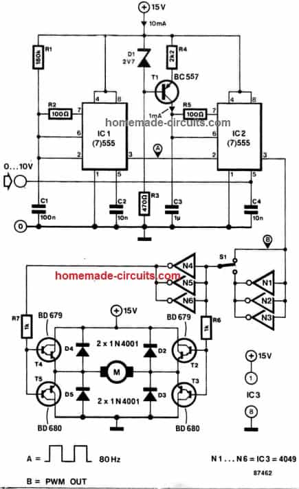
2) Bidirectional Motor Control using IC 556
直流电动机的速度和双向控制相对简单实现。对于独立通电的电动机,原则上是带有永久磁铁的电源电压电动机的线性函数是独立电动电动机的子类别,并且通常用于玩具和模型。
In this circuit, the motor supply voltage is varied by means of pulse width modulation (PWM) which ensures good efficiency as well as a relatively high torque at low motor speeds. A single control voltage he- tween 0 and +10 V enables the motor speed to be reversed and varied from nought to maximum in both directions.
Astable multivibrator IC is set up as an 80 Hz oscillator, and determines the frequency of the PWM signal. Current source T1 charges Ca. The sawtooth voltage across this capacitor is compared with the control voltage in 1C2, which outputs the PWM signal to buffer N1-Na or NPN1. The darlington-based motor driver is a bridge circuit capable of driving loads up to 4 Amps, provided the run-in current stays below 5 Amps, and sufficient cooling is provided for the power transistors T1 -Ts. Diodes D1, D5 afford protection against inductive surges from the motor Switch S1 makes it possible to reverse the motor direction instantly.
Prototype Images


swag.i want h bridge circuit whixh is capable of 50 amp with 12v to 36v with highly accurate and highly robust. i want this circuit for my robo war . and i also need your suggestion about wepon motor for robo war which i must buy . i want highest rpm with hightest torque. please suggest.
Hi Muhammad, if you are looking for high current and high accuracy system then you will have go for a BLDC 3 phase driver circuit, such as this one:
//www.addme-blog.com/2017/08/high-current-sensorless-bldc-motor.html
Because 50 amp is huge a 3 phase motor will work better than a single phase system. Moreover it also includes a reverse forward facility and it works with sensorless motors.
对于电动机,您还可以选择50安培35V BLDC,所有BLDC电动机将在高RPM处提供出色的扭矩
ok just ignor the acuracy . i need to just move a my 3kg blade by motor with aprox 6000rpm with higest torque . i am lil confuse of using moters.plese help me .and also for driver.
also suggest me 2 moter to drive a 50kg robot with speed.
understood, but still since 50 amp is huge a BLDC will work more efficiently, and will be very compact. Induction motors can be heavy huge and not so efficient.
Halo swagatam, i want to make a mini wiper from dvd motor which running on lithium battery. can you give me a schematic diagram for it (if possible use transistor only)? Thank you and sorry for my english
Hello Uchi, you can try this
//www.addme-blog.com/wp-content/uploads/2019/10/motor-control.jpg
Swag,
I am looking for a circuit design for a motor control for a 110v outlet. The power is activated by a microswitch.
This would be for a 2 hp motor dust collector.
Here is a link for a similar system, this one is for 220v.
They used to make a 110v one but discontinued it and that is what I need. I could buy a wireless/remote control one but I like to have the hardwired control.
Is this something you can help me with?
Thank you.
嗨,保罗,
I would recommend the 4) circuit from this article:
//www.addme-blog.com/build-these-simple-flip-flop-circuits/
Just make sure the triac is a 30 amp 600 V rated
I am assuming that the input supply is from a 110V AC outlet
Hi Swag,
Could you design a circuit for an electromagnetic bearing(Active magnetic Bearing) that can support large shaft with more than 500,000 RPM.
对不起,赫贾齐,我不知道这个巡回赛。
我一直在研究双向直流电动电路设计,以启动一个小型直流蠕虫驱动电动机,该电动机将在我的多发动机无线电控制飞机设计上操作舵。我的想法是将叶片连接到电位器上以感知气流,从该信号中,控制我的蠕虫驱动电动机以将飞机舵放置在一个发动机关闭时控制飞机偏航。您的LM 324电路绝对比我所设想的要领先。我从未考虑过脉冲宽度调制。我认为这可以解决我以前的绊脚石的设计块,该块在Yaw Sense Vane上大约一个1或2度的死区域,因此当偏航处于所需的角度时,偏航执行器不会来回振荡。(通常为0度)。0度偏航提供了最低的阻力,因此是最佳的一个发动机操作攀登性能。我还考虑了添加由舵伺服器控制的锅,该锅可能会以某种方式替换R6,R7和R8电阻电路,以便我可以控制偏航角并对飞机有更多控制。
您能否提供R1,R2和P1的电阻值的想法,这会使偏航传感器变得更敏感并为伺服控制的偏航控制有建议吗?
The other addition that I don’t think would be to hard to design are limit switches for the rudder actuator motor and an airspeed switch to disable rudder positioning until the aircraft is up to flying speed.
An additional idea I’ve been considering is using two micro pressure sensors that would compare static pressure on the left and right side of a small vertical airfoil. The idea being that if the aircraft is not yawing the pressures would be equal but would differentiate in proportion to the aircraft yaw angle.. This would decrease the amount of moving parts (Reliability) and eliminate the need for an airspeed switch mentioned previously.
Thank You
Jim
I appreciate your ideas and sincerely hope they will work, but since I have no expertise in the aviation field or relevant mechanical operations, interpreting the system may not be possible for me.
However, as far as the first circuit is concerned, the adjustment of P1 will allow an equivalent amount of pulse width supply for the motor, meaning if the P1 is moved more towards the ground line, the motor will get reduced equivalent pulse width voltage and therefore will rotate slower, when P1 is moved towards the positive line, the pulse width will be wider causing the motor to rotate with higher equivalent speed.
In order to get a wider range you can simply remove R1 R2, which will allow the load to be operated from 0 to 100% power across the applied voltage range, depending on the P1 position.
for Mr. Jim Ransom.
Hello.ALL auto-pilot’s for a ‘yaw-control-line’ are based on vertical-supervisors (VS)!!!!! Simplest VS is a jointed to a potentiometer arm with a weight as a simplest kind of 3-pendulum’s VS. 1-st potentiometer’s pendulum’s arm is rotated = nose-aft. 2-nd= left-right wings. Both 1st and 2nd are vertical plane’s. 3-rd is for = horizontal rotation plane. All 3 planes potentiometer’s signals given to a analog/digital system (ADS) for calculating of a necessary rudder’s deflection angle. Than by a feedback potentiometers from rudder’s actuators the ADS can predict necessary deflection angle for a auto-pilot’s neegs = anti-turbulence function via very elaborated computations.
佛r you same – for a simplify – from the left-right potentiometer = P1 (100K of 1-st circuit) – direct to other elements of the 1st circuit but shell be a ‘zero-power to motor’ at +/- few degrees of angle of the potentiometer – against vibrations and a small oscillation influences.
Como vai? gostaria, de mover um motor de aproximadamente de12v AC, com esse circuito seria possivel? obrigado.
嗨,对不起,无法使用上述概念来控制交流电机。
Please sir I want to used one of this circuit to control car kit BLDC motor, will it work?
BLDC are 3 phase motors, the above circuits are for brushed motors, not for BLDC