
The article discusses a protection circuit which may be used for preventing a "dry run" situation in mini coffee dispenser motor pumps, by sensing the slight difference in its wet and dry current consumption levels. The idea was requested by Mr. Ken Adler.
Technical Specifications
I read with greatinterest your post titled, "Motor dry Running, Tank Overflow Water Level控制器电路。“我们在微型方面也有类似的问题hot water pump used in coffee machines. (see attachment).
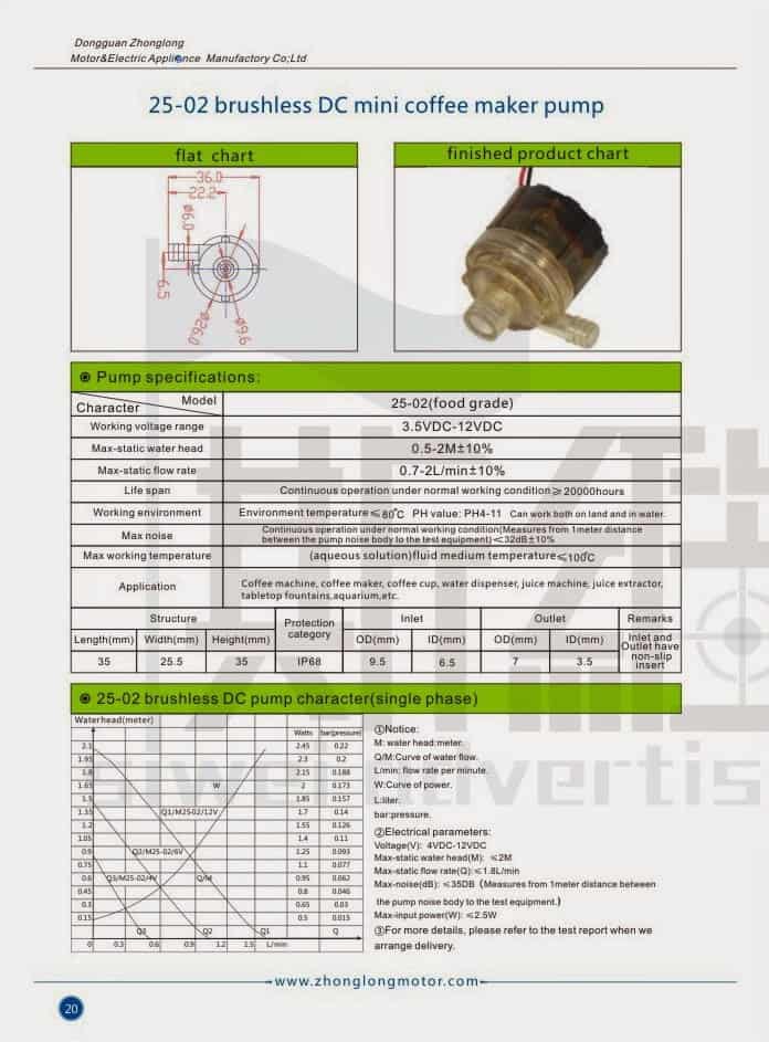
泵通常以0.15至0.25安培和4.5至6伏的速度运行。上面的数据提供了最大的操作条件。
泵的一端有一个电路板。
I've attached a very rough picture. Ultimately,
I'd like the manufacture to modify the circuit board to include the dry run protection. We need a very small circuit designed that would sense a change in current when the water level is below the pump.
请注意,泵很小,需要将电路集成到现有的板上。
您能为此应用设计电路吗?如果是这样,您将收取多少费用?
干杯,
Ken Adler
President
鹰设计
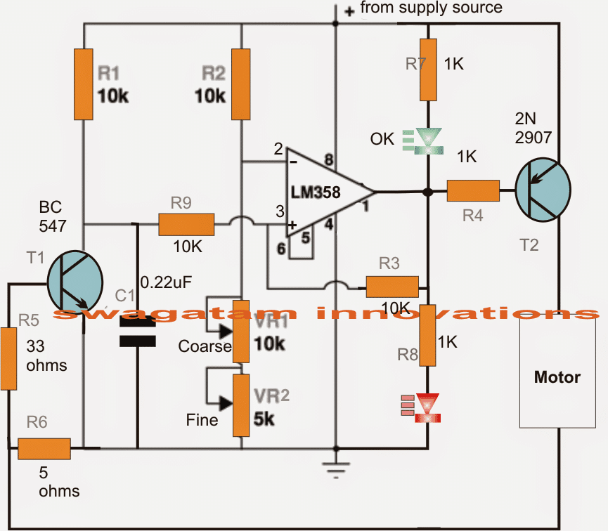
The Design
请求的迷你咖啡泵干燥的保护器电路可以在下面的图表中看到,并且可以在以下几点的帮助下理解:
When power is switched ON, C1 pulls the non-inverting input pin3 of the opamp to ground so that an instantaneous low is developed at the output of the opamp.
在输出触发T2处的瞬时低点又启动了连接的咖啡泵电动机,该电动机被假定在此处加载带有流体含量。
电动机开关导致额定电流流过R6,从而将其转化为比例的跨自身和T1底部的电位差。
This prompts T1 to conduct and sustain pin3 of the opamp to ground so that T2 is able to hold the pump motor in the switched ON state.
Now suppose at some point of time the fluid level drops below the threshold forcing the motor to run dry, the motor current consumption also drops to a proportionate degree such that the potential across R6 becomes low enough to switch OFF T1.
As soon as T1 switches OFF, the potential at pin3 jumps above that of pin2 rendering a high at the output of the opamp which instantly switches off the motor preventing it from the "dry run" situation.
R3 makes sure that the situation gets latched ON and stays in that position until the tank gets filled and the circuit is reset by a complete switch OFF and switch ON.
Circuit Diagram
How to Set up the Circuit
- Initially keep R3 loop disconnected
- Also, disconnect the motor positive from the T2 and connect it directly with the positive of the supply so that while testing in switched ON condition the motor simulates a dry run situation (low current run)
- Now switch ON power, let the motor spin, and by little trial and error adjust VR1/VR2 until the red LED just comes ON, while the green LED shuts off.
- The pump dry run circuit is all set now, restore the R3 and the motor positive connections back to their original positions, test run the circuit under actual conditions with tank filled and empty for witnessing the intended protection features of the circuit.

Your Comments are too Valuable! But please see that they are related to the above article, and are not off-topic!