
该帖子解释了根据个人要求定制的几个有趣的计时器电路。
第一个是仅在一周的某些选定日子内,用于在预定时间内驱动电动机的一种每周/天的可编程计时器电路,而第二定时巡回赛则用于向讲师提醒有关他////////她的上课期。
Stevan先生和Ilman先生要求这些想法。
Circuit Request#1
I spend more than 20 hours on your site, searching for a circuit I need...
我的知识还不足以弄清我可以使用哪个电路,我尝试了许多电路...如果您有时间,如果您能帮助我并设计电路,我将非常感激。
我需要计时器电路,这将使我可以选择它将停留多长时间(3-10秒),以及在7天内重复该动作的次数(即一周一次,一周两次,每天等)。我需要它来控制9-12V电动机。
Circuit Diagram
Circuit Operation
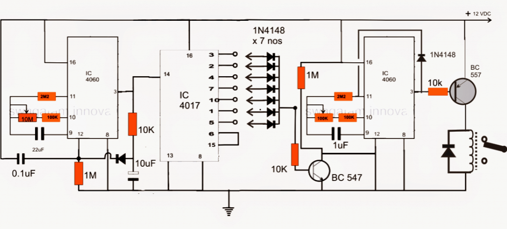
As shown in the above week day programmable timer circuit, the IC 4060 at the left side is wired up as a24小时计时器电路。
时间长度是由22 uf capacito决定r and the 10m pot. A suitable fixed value may be selected for these two components for getting the specified time delay.
22UF电容器必须是非极性低泄漏类型的电容器,电阻应为MFR 1%
The output is received from pin#3 of the above IC, which goes high as soon as the set time elapses. This results in a short pulse to pin#14 of the IC 4017 which is configured as a 7 stage counter divider here.
在预设间隔24小时之后的每个脉冲中,IC 4060还通过连接到其销钉#3和引脚#12的二极管重置。
IC 4017输出作为一个星期计时器,其7个输出的速度(较高)从PIN3转移到PIN6,依次响应上述24小时脉冲,描绘了一周中的7天。
右侧IC 4060被配置为短持续时间计时器,用于激活可能与显示的继电器触点连接的电动机。
This stage is integrated with the IC 4017 stage through the shown 7 1N4148 diodes. Depending on what days the motor needs to be switched ON, only those relevant diodes are connected with the 4017 outputs, rest of the diodes are kept unconnected.
在所有这些连接之后,当电源打开时,左侧4060触发器并迫使IC 4017的输出每24小时后每次序列高。
根据连接的二极管,right hand side 4060 IC gets switched ON only on those selected days of the week via the BC547 transistor which grounds its reset pin#12 on receiving the signal from the IC 4017 relevant outputs.
This prompts its pin#3 to go low activating the preceding relay driver stage and the motor.
The above stage stays activated until the set time elapses when its output becomes high inhibiting the relay driver sage from base drive thereby stopping the motor. The high from the pin 3 also latches the IC via the diode to its pin11. The time interval may be fixed by adjusting the given 100k pot
从24小时4060计时器阶段开始,整个操作重置下一个脉冲。
因此,操作按照在三个IC上完成的编程重复。
Circuit Request#2
I need circuit for time limiter to use for public speaking.
假设老师在课堂上有一个小时的讲话,那么计时器将从60分钟开始显示绿灯,然后降低到0,但是在完成之前,黄色的灯会打开以保持老师几乎结束,它可以在0到0之前3分钟,终于,当时间超过红灯时,这意味着老师的时间已经结束了。
Circuit Operation
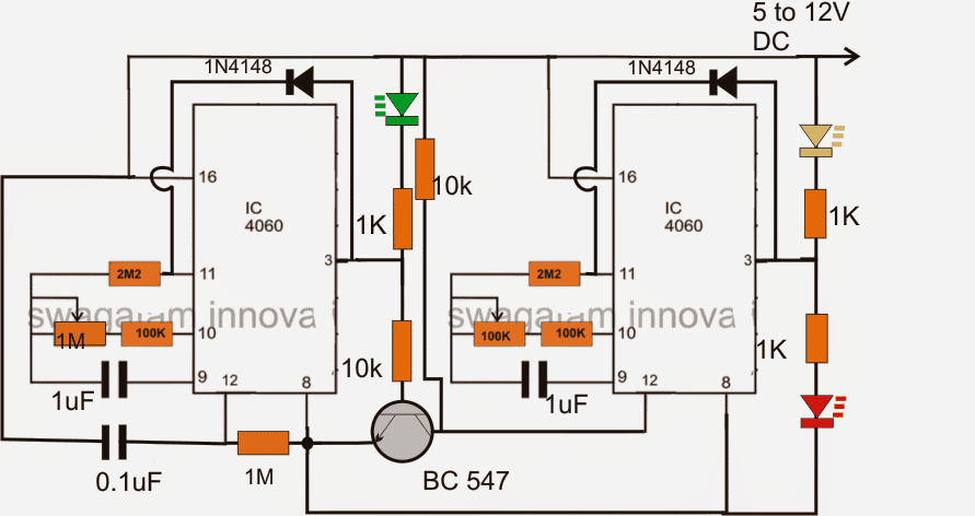
The above cascaded两级顺序计时器电路相当简单,其配置两个4060 IC相互链接,以形成顺序的计时器配置。
左IC被操纵为57分钟的计时器电路,而右侧IC作为3分钟计时器电路。
When switched ON the left IC starts counting (green LED ON) until 57 minutes have elapsed which makes its pin3 go high, shutting off the green LED
这触发了连接的BC547晶体管,该晶体管现在将第二个4060 IC的PIN12接地,从而促使其开始其3分钟的计数过程。
这激活了黄色的LED,指示最后3分钟计数,直到它被关闭了黄色的LED并打开红色LED。
ICS的PIN3和PIN11上的二极管保持IC锁定,直到电路关闭并打开,以启动下一个周期。
使用LDR检测日夜时间
基本策略是产生一个电子信号,该电子信号一旦太阳落下,随着黎明的落入而变低,然后计算过渡。Photocel1 LDR1的位置可感知太阳光。这必须针对北天而不是直接的太阳,因此在晴朗的天空和铸造的天空中,它几乎会看到相同的东西。R1用于控制LDR的灵敏度。
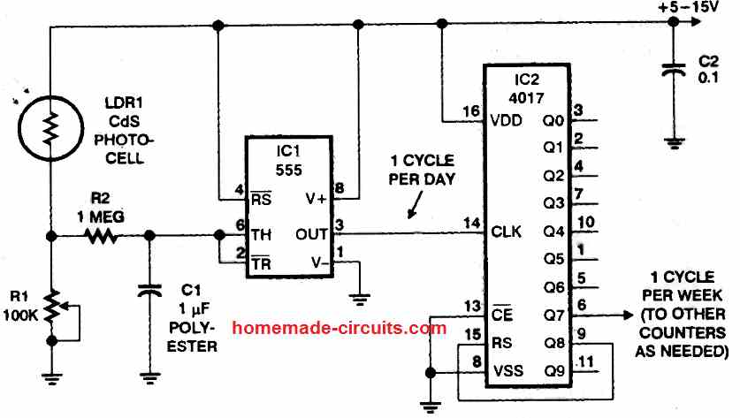
在不处理完整的白天/夜间的情况下进行微调的一种好方法是停止直到日落后10分钟,在白天和夜晚之间的中心旋转,并更改R1,以使其对面的电压为一半的电源电压。
稍后,检查IC1在夜间的输出高,白天很低。使用R2和C1创建低通滤波器,大约产生1秒钟的固定,以确保电路不会被闪电闪光或其他各种短暂的光变化嘎嘎作响。
555个计时器ICI像光级传感器一样使用;而不是比较器电路。555提供磁滞,这意味着电压上的扳机将大于扳机电压。
这可以防止过渡阈值期间和在OFF之间的“口吃”和FRO的“口吃”。电路中的第二个IC(IC2)是4017(CD4017)CMOS十年计数器。
只需将输出Q8连接到重置输入即可,我们允许它计算到7个,然后重新开始,因此其输出每周会产生一个孤独的一天的脉冲。您可以将其提供给其他计数器,以计算甚至延长的时间段。
For instance, incorporating a divide-by-four counter (like a 4017 with Q5 attached to reset) could give you a period of 28 days

亲爱的斯瓦加塔姆,非常感谢您的这一巡回赛,解释和您的时间!我只有两个问题……
You wrote "Depending on what days the motor needs to be switched ON, only those relevant diodes are connected with the 4017 outputs, rest of the diodes are kept unconnected" – Does it mean that motor can be turned ON for example 2nd day and 4th day?
我的第二个问题是关于 +12V和地面,因为它看起来很短。
再次感谢…
亲爱的史蒂文,
Thanks! Yes the motor can be switched ON on any particular selected days of the week.
I have corrected the diagram, the short is removed now.
谢谢大师…
It works by little bit correction in pin 8 (IC2) should be opened from ground.
我的下一个问题是关于连接到引脚9和10的电阻和电容器的公式,因此我可以计算所需的时间。
Thanks for your help.
Gumilar
Gumilar,如果您断开任何ICS的PIN8,则会导致电路故障,因为它是IC的地面引脚。
For the formula you may refer to this article:
//www.addme-blog.com/2012/01/how-to-make-simple-versatile-timer.html
Respected Sir,
我爱你的博客。我花了很多时间来搜索倒数计时器开关的电路120V,但找不到。您可以上传一个还是可以指导我同样的?
谢谢你
shah
克里斯汀(Kristin),请提供有关您要求的更多详细信息,我将尽力提供帮助。
Dear Swagatam Majumdar
我是shouquat。我喜欢你的工作。我可以知道,如何检查7天的每日电路吗?它是否有效。因为如果它可以正常工作,但要等待很长时间才能查看结果。您能给我一些想法来快速检查电路吗?问候,
很想看到一个将LED打开4个小时的电路,然后入睡20个小时。我制作LED蜡烛设置的一部分。
您可能可以尝试以下设计:
//www.addme-blog.com/how-to-make-simple-programmable-timer/
在电路中的20小时阶段,使用许多1UF非极性CP并联C1
Love all your work!
如此多的祝福。
Old ET. From tubes to transistors and ICs.
享受一切。
沃尔特。s
非常感谢,很高兴您喜欢我的工作,请继续努力!
las publicaciones son excelentes,por lo básicas que son ,me han ayudado a comprender el funcionamiento de muchos aparatos electrónicos y mecánicos de la manera mas simple,por lo que esto me permitido poder interpretar planos y maquinas mas complejas.
Bueno no Puedo Escribir Muy Bien Ingles Pero Si Pudo Traducir Perfectamente。
âgracias!Realmente aprecio sus pensamientos y me me alegro de que le hayan gustado misartículos,\ sigan con el buen buen trabajo!
Hello,
Thank you very much, the first circuit is perfect for a project I am working on. I’m relatively new to circuits and I wanted to try to understand what is happening a little more. Could you explain the purpose of some of the components for me?
10m锅如何更改4060频率的计算?每次我尝试使用您在4060解释的文章中给出的公式时,要么从您提供的内容中计算出频率,要么尝试从我想要的频率中计算出电阻,我的答案就永远不会匹配。
二极管跨引脚#3和引脚#12的目的是什么?当我查看这篇4060文章时,似乎并不是必需的,是否还需要吗?
What is the purpose of the 10 uF polar capacitor between pin#3 and the ground?
Sorry for all the questions, I’m just hoping to learn more.
You are welcome, and appreciate your feedback.
10m形成了补充正时电容器CT的正时电阻。借助与RT,CT相关的IC内部门的作用,通过RT向CT充电并通过RT进行充电。
In the formula you must use Ct in Farads, and Rt in Ohms.
二极管导致即时重置和振动引脚#3至零,以便下一个计数能够从完美的零开始,这确保了IC 4060的准确均匀的正时脉冲。
The capacitors ensures that pin#14 gets a proper logic from pin#3 and the IC 4060 is erset after some delay, allowing pin14 of the IC 4017 to implement the changeover correctly.